Assembly
Before starting assembly
- Check the components are complete. See BOM.
- If you are not used to soldering, learn how to solder components.
Soldering
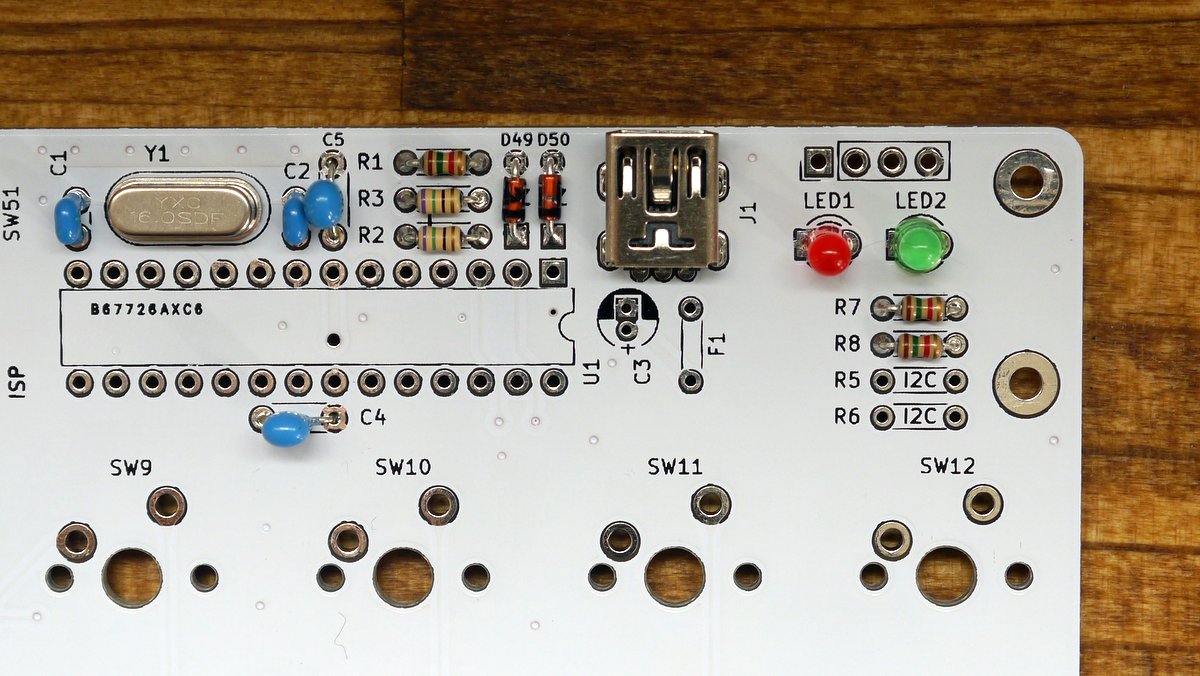
Zener diodes (D49,50)
Solder D49 and D50.
Diode is a polarized component and therefore take care of direction.
A Black line on diode is cathode. (square pad on pcb)
Resistors (R1,2,3,4,7,8)
Solder resistors. Don't place on R5 and R6. (They are for i2c)
| Ref | Value | Color code |
|---|---|---|
| R1,7,8 | 1.5k | Brown/Green/Red/Gold |
| R2,3 | 75 | Purple/Green/Black/Gold |
| R4 | 10k | Brown/Black/Orange/Gold |
| R5,6 | I2C | Do not place |
Diodes 1N4148 (D1-48)
Diode is a polarized component and therefore take care of direction.
A Black line on diode is cathode. (square pad on pcb)
Crystal
Capacitors (C1,2,4,5)
There are 2 kinds of lead pitch.
| Ref | Value | Lead pitch |
|---|---|---|
| C1,2 | 22pF | 2.5mm |
| C4,5 | 0.1uF | 5mm |
USB connector
Narrow pitch! Be careful of solder bridge between pins.
LEDs
LED is a polarized component and therefore take care of direction.
A short leg is cathode. (square pad on pcb)
If you use leds, make bridge J4 and J5 on bottom side.
IC socket
Solder IC socket.
IC socket is a polarized component and therefore take care of direction.
Check the notch on silk and IC Socket.
Electrolytic capacitor(C3) and Resettable fuse(F1)
Electrolytic capacitor is a polarized component and therefore take care of direction.
A short leg is cathode. (square pad on pcb)
And after soldering resettable fuse, bend like the image.
Tactile Switch(SW50,51) and pin header
ATMEGA328p
Insert ATMEGA328P into IC Socket.
ATMEGA328 is a polarized component and therefore take care of direction.
See the image.
Check list before connect USB
- No short between VCC and GND, USB connector pins.
- Direction of polarized components.(ATMEGA328p, diode, resettable fuse, electrolytic capacitor)
- Resistor value